1、 Problem posing
When turning threads on a CNC lathe, the following problem is often encountered: (1) the thread cutter is damaged halfway through the thread turning process. (2) I want to switch to a high-speed precision threading tool for threading. (3) After removing the threaded car and measuring again, it was found that the depth was not enough. When encountering these same problems, we often feel helpless because after changing the tool or re clamping the workpiece, the threading tool is difficult to align with the original spiral groove, the starting position is not accurate, and the teeth are always messy.
2、 The principle of turning threads on a CNC lathe
To solve these problems, we first need to understand the principle of CNC lathe turning threads. To complete the cutting of threads, it is necessary to accurately achieve one rotation of the workpiece and one lead of the tool feed. In order to achieve this, a spindle encoder is installed on the CNC lathe. Its synchronous pulse is used as the cutting control signal for the tool's feed and exit points, enabling the tool to advance
There is a corresponding relationship between the number of pulses given to the servo motor and the spindle speed. However, due to the lack of direct mechanical connection between the rotation and feed motion of the CNC lathe spindle. So when reinstalling the tool or workpiece, it is not easy to achieve cutting along the original spiral groove with the tool tip.
3、 Existing prevention and control measures
At present, when using CNC lathes to turn threads in enterprises, most of them use a single clamping tool for turning. Both coarse and fine use the same blade at the same speed. If the knife breaks halfway, do not remove the knife holder and replace the blade directly to prevent tooth misalignment. But if the rough and fine cutting tools are separated for turning or re clamping of parts, it will bring about the problem of messy teeth.
4、 Methods to solve problems
If the cutting tool is damaged during the threading process or if you want to replace it with a precision cutting tool for threading. After the new knife is installed, simply re align the knife. When aligning, it is easier to align in the x direction, but the key is to align in the z direction. Many people move the blade tip to the end face of the workpiece based on their intuition, as shown in Figure (1). This way, the knife error ratio
Larger, the rough car is okay, but the fine car is not. Here, I will introduce a method to everyone. You can use existing angle templates or create your own template, as shown in Figure (2). Accurately measure the distance of L in the graph.
When aligning the tool, as shown in Figure (3), place the template against the end face of the workpiece, move the tool into the inner corner of the template, and then input the Z-force to the tool compensation value L into the system. This tool alignment method has high accuracy and is suitable for precision machining.
2) Repair of single or small batch threaded parts
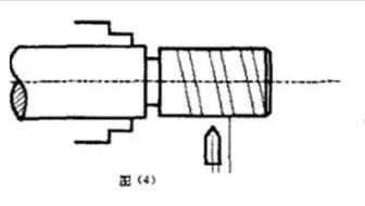
If the threaded part is removed after being installed, it is found that the depth of the teeth is not enough and needs to be repaired with a new clamp, which is quite troublesome. Firstly, to solve the problem of jumping after reassembling the parts, an open sleeve can be made to eliminate the error of jumping. I believe most people know this method, so I will not explain it further. The remaining task is to solve the problem of cutting along the original spiral groove to prevent tooth misalignment. This problem is easy to solve on a regular lathe, but more difficult on a CNC lathe. The method adopted by many people is shown in Figure (4).
After aligning the knife, make sure it does not touch the parts and run the thread at a slow speed without processing the program. Measure the distance L from the blade tip to the spiral groove, and then repair the starting point of the thread cutting in the program. Shift it from point A by a distance L to point B. Repeat the above process again, adjusting the distance L. Repeat this process until the cutting edge cuts into the threaded groove. This method requires constantly adjusting the distance of L, which is very time-consuming. Actually, we can make slight modifications to the original program to solve these ten problems. Just change the thread length in the program to around 2mm. The workpiece is clamped properly. After aligning the turning tool, call out the program. Turn on a very short thread and find the starting position of the thread on the end face, as shown in Figure (5).
Assuming that the starting position of the thread of the new car is at point 2, while the starting position of the original thread is at point l. Draw a line AB along point 2 on the chuck, and then release the claw. Rotate the part from point 1 to point 2 towards the marked line AB. If there is axial movement of the workpiece during rotation, the thread cutter must be re aligned in the z-direction.
Clamp the workpiece and change the length of the thread in the program to its original value. Run the program once to test cutting, check the error, and adjust the starting position of the thread cutting slightly based on the error. As for the thread just cut from point 2, it can be removed by chamfering due to its short length. This method of repairing screw debris is much faster and more accurate than the previous one, and the key step is to accurately rotate the part from point 1 to point 2.
If there is a small batch of threaded parts that need to be repaired, we can use the original program to make a new thread, find the starting position of the thread, draw a line on the chuck as a mark, and use the above method to repair.
 العربية
 简体中文
简体中文 Nederlands
 English
 Français
 Deutsch
 Italiano
 日本語
日本語 한국어
한국어 Português
 Русский
 Español